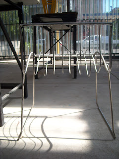
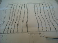
This collage of images depicting both the original and re-designed prototype provides a visual distinction, or in this case, a correlation between old and new. The exagerated curve and 'fin' lines have been reinterpreted in the new seat frame, which curves and falls in much the same way as the orignal. The lightweight nature of the original has been retained by having a transparent shell, that is easy to pick up and move around. To sit on the chair is semi-comfortable, okay for a short period making it appropriate for cafe culture. A degree of flex is detectable, but the back is too sharp and you can find yourself sliding forward. As a prototype i am very happy with the result, its sturdy, true to my initial vision and drawings and the minor variation in the steel rod seat surpasses my original expectations. If i was to further develop my chair i would use machine precision technology for the bending and a revised backrest with the possible inclusion of a leather seat pad. In terms of finishes, i could also pursue the idea of having a chrome base with powdercoated seat and frame. A combination of colours would also be visually effective.
Monday, 14 November 2011
Final touches- painting
The finished chair sprayed in the workshop. Spraying proved difficult for achieving an even coat but the result was rewarding.
Close-up of my handy paint-work.
I chose 'black' but the chair would look good sprayed in any other bright colour due to its simple form.
Close-up of my handy paint-work.
I chose 'black' but the chair would look good sprayed in any other bright colour due to its simple form.
Welding, filing and Sanding- Work in Progress
Sanding and filing the chair in preparation for it to be painted.
The welded joins needed to be well filed and sanded to ensure a neat and consistant finish. Attention to detail is imperative in my chair design due to its simplicity of materials and construction.
Close-up shot of my welding, grinding and sanding technique.
The waving contour of the seat profile is evident in this picture. The steel dips and dives evoking a sense of movement and energy.
I opted to use a matte black primer to finish my chair- i think it produces a finish that is just as good as powdercoating and it allowed me to finish my chair without any external help from the workshop. Its affordable, convenient and only requires a couple of good coats.
Friday, 4 November 2011
Workshop Progress
Using my 1:1 drawings of the chair and the mock-up frame i welded earlier in the semester i cut out a jig template to use as a guide for cutting the steel rods that make up the 'seat' of my chair. The jig was machine cut (saw) and sanded to achieve a smooth, curve profile.
The jog was clamped to the workbench and the rods cut to about 1200mm lenghts. We worked out a bending system of firstly creating the hook curve of the seats back. This was created using a combination of sheer manual hand-bending, roller-bending, banging and lots and lots of hand manipulation.
The bending of the steel took an enormous amount of time and energy, 4 full-days for 8 lenghts of steel in fact. Because of the lenghty process i decided i would have to make do with the 8 and difference in thickness by increasing the spacings and contour of the curve. By tacking the steel to the frame i decided on having 6mm rod on the outer-side and the remainder 4mm steel to the centre for a harmonious and even composition.
With some assistance i tack welded (mig) the steel to the steel frame having grinded off the temporary legs.
Monday, 3 October 2011
Design Development Review - Model & Drawings
 |
| Exploded perspective line drawing showing assembly with all components labelled. Model created using 3D AutoCAD, Adobe Photoshop and In Design. |
 |
| Perspective rendering of final design showing all configurations. Model created using 3D AutoCAD, Adobe Photoshop and In Design. |
 |
| Side elevation showing human figure |
 |
| In-class hand-sketched 1:1 Side elevation drawing for ergonomic checking |
Wednesday, 21 September 2011
Chair Prototyping
On the 21/9 I spent the day working on a basic prototype of my chair with the assistance of Bernie from the Workshop. My aim was to determine the right method, materials and machinery for the manufacture of my chair. We began by removing the plastic shell off the chair and sourcing appropriate steel rods for the frame and shell of the chair. Using coat hanger wire we moulded various profiles of the chairs shell to use as a guide. Using the jig we began hand bending the steel, this process was easy and not physically arduous, however, we discovered using tubular steel would be swifter and make for a lighter frame. Next we arc welded two parallel steel rods to the side profiles to form our seat shell frame. Arc welding is moderately difficult but ensures strong bondage of joins. Our next step was placing the frame on the base to determine how it was to be fixed and also how the inner steel rods that form the seat would be joined. We realised the seat needs to have a degree of flex to be comfortable to seat in which requires rods of a certain diameter and length of span. The seat should also not have a base that interferes with its sagging in weight, hence, our decision to remove the three steel braces off the base with a power saw. What remains to be resolved is how to suspend/fix the rods to the frame and how much flex should be allowed? I have ordered in 6-8 meters of 6mm mild steel rod to test this aspect of my chair design.
 |
| Hand bent and welded solid steel frame on existing sled base |
 |
| Clamps used to hold frame in position while welding temporary legs |
 |
| Jig used to bend steel rod for frame. A hammer was then used to straighten the rod. |
 |
| Quick welding job to form an outer frame for the shell of the chair. Tubular steel is proposed for the final prototype. |
 |
| Basic steel section/profile. To be reused as a guide. |
 |
| Bernie cutting off the base bracing using an angle grinder. |
Monday, 12 September 2011
Sunday, 11 September 2011
Thumbnail Sketches
I started my sketch design phase by drawing the purchased chair and noting all its positive redeemable features as well as its flaws. This helped me distinguish what aspects needed improving, rejecting and reinterpretation in the re-design. I then started drawing any curves evident in the purchased chair exploring how they could inform features of the new design ie. arm rests, curved legs and backrest. Considering the base was in good condition i decided to leave it as is and focus on the 'curve' feature for the shell of the chair. By tracing the existing profile of the chair with bent tubular steel i am reinterpreting the original style of the chair and utilising feasible workshop technology. I finally deliberated on three concepts;
1. Bent tubular steel frame with bent steel rod slats on original sled base
2. Bent tubular steel frame with timber inserts for seat and backrest on orignal sled base
3. Bent tubular steel frame with timber seat and backrest featuring pattern cut-out on original sled base
 |
 |
| Quick hand sketches showing conceptual design development. |
Monday, 5 September 2011
Chair Exemplars
Subscribe to:
Comments (Atom)


